As industrial internet, artificial intelligence, and IoT technologies rapidly advance, the Variable Frequency Drive (VFD) industry is evolving toward greater intelligence and digitalization. Beyond their traditional roles in speed regulation and energy savings, modern VFDs now incorporate remote monitoring, fault prediction, and adaptive control technologies. These innovations enhance operational efficiency, improve system stability, and contribute to global energy conservation and emission reduction goals.
Geehy 2.2kW High-Performance Vector VFD Solution Overview
The Geehy G32R501 2.2kW high-performance general-purpose vector VFD solution is designed for precise speed and torque control of three-phase AC synchronous motors. Utilizing advanced vector control technology, it delivers high torque at low speeds, ensuring excellent dynamic performance, exceptional overload capacity, and user-programmable functionalities. The solution also supports comprehensive back-end monitoring through integrated software. Featuring communication bus support for multiple PG cards, it offers stable and powerful performance, making it ideal for a range of automated industrial equipment, such as textile machinery, paper mills, wire drawing machines, machine tools, packaging machinery, food processing systems, and fans and pumps.

Key Parameters

VFD Block Diagram
Hardware & Software Overview
The G32R501 2.2kW VFD solution includes a power board, control board, and key display board.

VFD Figure
This solution utilizes a sensorless observer to achieve high-performance sensorless FOC control, with a speed regulation range of 1:200, speed accuracy of ±0.5%, and torque accuracy of ±0.5% (above 5Hz).

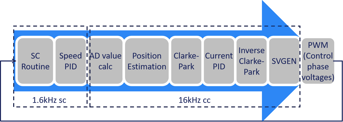
VFD Sensorless Control Diagram
Solution Advantages
· Single-chip solution based on the G32R501 real-time MCU
· Zero-speed switching for smooth and continuous operation
· Static motor parameter identification (resistance/inductance/flux linkage)
· Ultra-strong overload capacity for synchronous motor drives
· Carrier frequency range: 0.8kHz–16kHz, automatically adjusting based on load characteristics
· PI self-tuning: Automatic optimization of control parameters, improving control accuracy, dynamic response, and stability

With the G32R501 chip running at 240MHz in single-core FLASH execution mode (path: ITCM → FACC → Flash), the control loop period is optimized to 62.5μs, and in O2 optimization mode, execution time is <19.8μs, outperforming similar products (24μs).
|
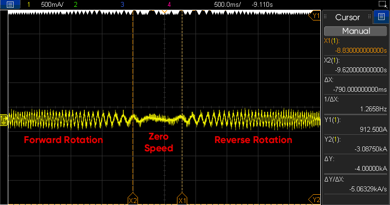
Zero-Speed Forward & Reverse Switching |
Enables seamless forward and reverse operation at zero speed. Optimized control strategies ensure a smooth transition zone and switching logic, while a state-machine hysteresis method prevents mechanical reversals during direction changes. |

|
IPD Initial Position Detection |
Utilizes the pulse injection method to estimate the rotor's initial position. The 0–360° electrical angle range is divided into N segments, where equal-amplitude pulses are applied to collect AB-phase currents. Due to the rotor's magnetic influence, the current change rate is higher in the S pole direction and lower in the N pole direction. The segment with the highest current change rate determines the electrical angle, which, combined with the assumed initial angle, identifies the rotor’s position. Additionally, jitter compensation can be applied using the incremental optical encoder values. |
|
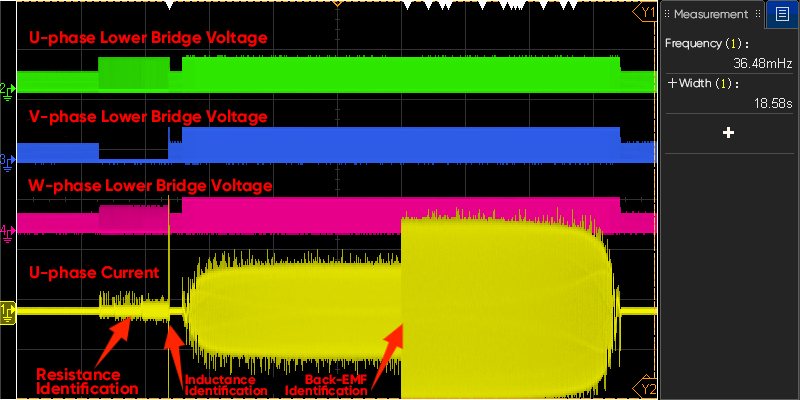
Motor Parameter Identification |
It enables static motor parameter identification (resistance, inductance, back EMF) and PI parameter self-tuning with one-click operation, eliminating manual adjustments. · Resistance Identification: Uses the DC injection method by applying DC voltage to the motor windings and measuring the resulting current. Resistance is calculated using Ohm’s law, with low-pass filtering for accuracy. · Inductance Identification: Utilizes the pulse voltage method, injecting high-frequency pulses along the d and q axes in a two-phase rotating coordinate system to calculate inductance. · Back-EMF Identification: Employs a state observer to estimate rotor position, speed, and current, enabling precise back-EMF observation. · PI Parameter Self-Tuning: Establishes a closed-loop motor model, using critical gain and period to determine optimal Kp and Ki values. These technologies enable high-precision sensorless motor control. |
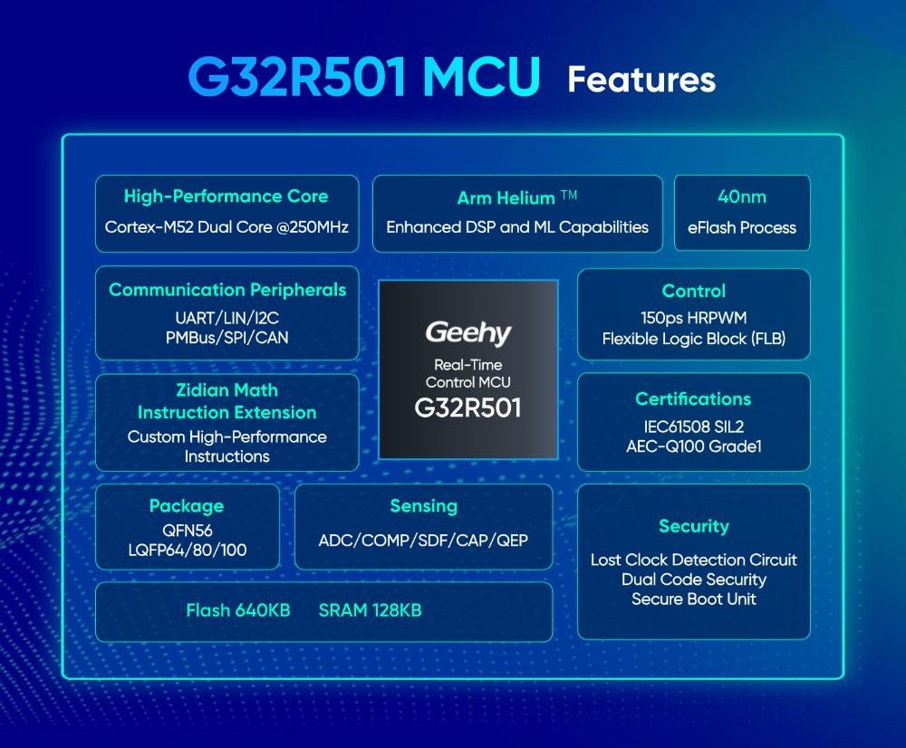
G32R501 Chip Features
· Core & Memory: Cortex-M52 dual-core architecture with 250MHz frequency. Equipped with ITCM, DTCM, I/D-Cache, Flash prefetch, and high real-time performance.
Extended Instructions: The Proprietary Zidian Mathematical Instruction Extension supports CRC, Viterbi, trigonometric functions, division, square roots, and more.
· Enhanced Control Peripherals:
· 16 PWM channels with high synchronization for precise low-speed motor control.
· Flexible IP linkage with two additional comparison sub-modules (CMPC, CMPD) for synchronized event generation, PWM phase alignment, and ADC triggering.
· High-Precision Analog Peripherals:
· Three 12-bit ADCs at 3.45MSPS for fast and accurate signal acquisition.
· Supports 3.3V/2.5V internal references, with a 2.5V option improving voltage resolution by 32% for enhanced feedback accuracy.
· Comprehensive Communication Interfaces: CAN×2, I2C×1, UART×2, SPI×2, QSPI×1, LIN, PMBus×1.
Geehy's G32R501 2.2kW High-Performance Vector VFD Solution offers a comprehensive software and hardware package, including a PC-based debugging tool for parameter configuration, JOG debugging, fault diagnosis, and waveform analysis. A detailed user guide ensures quick evaluation and seamless custom development for engineers.